- English
- Español
- Português
- русский
- Français
- 日本語
- Deutsch
- tiếng Việt
- Italiano
- Nederlands
- ภาษาไทย
- Polski
- 한국어
- Svenska
- magyar
- Malay
- বাংলা ভাষার
- Dansk
- Suomi
- हिन्दी
- Pilipino
- Türkçe
- Gaeilge
- العربية
- Indonesia
- Norsk
- تمل
- český
- ελληνικά
- український
- Javanese
- فارسی
- தமிழ்
- తెలుగు
- नेपाली
- Burmese
- български
- ລາວ
- Latine
- Қазақша
- Euskal
- Azərbaycan
- Slovenský jazyk
- Македонски
- Lietuvos
- Eesti Keel
- Română
- Slovenski
- मराठी
- Srpski језик
- שפה עברית
- беларускі
- Bosanski
- ქართული
- O'zbek

How DC Contactors and Fuses Work Together?
One manages controlled switching; the other provides passive protection—how do they coordinate?
In the main power circuit of a DC charging station, the DC contactor and fuse form the most critical dual-layer protection barrier. One performs the controllable switching function; the other serves as the ultimate passive defense line. Their roles are clearly defined, yet they must operate in precise coordination.
Many engineers habitually select these two devices independently during system design. However, practical engineering experience demonstrates that improper coordination can lead to consequences ranging from protection failure to equipment burnout or even safety incidents. This article systematically analyzes the coordination and matching principles of DC contactors and fuses in charging stations from the perspectives of technical principles and engineering practice.
I. Functional Definition: A Dual-Layer Protection Architecture with Clearly Defined Roles
DC Contactor: A Controllable Executive Switch
A DC contactor is an electromechanical switching device that connects and disconnects high-power DC circuits under control system commands. Its core functions in a charging station include:
•Charging Start/Stop Control: Closes to establish the charging path upon command from the BMS or charging controller, and opens to disconnect upon completion.
•Emergency Isolation: Executes controlled power disconnection upon receiving commands when the system detects abnormal conditions such as over-temperature, over-voltage, or insulation faults.
•Pre-charge Management: Works with a pre-charge resistor to limit inrush current before the main circuit is energized, protecting the bus capacitors.
DC Fuse: A Passive Ultimate Protection Device
A fuse is a single-use protective element that reliably interrupts fault currents before they cause irreversible damage. The fundamental differences between semiconductor-grade fast-acting fuses used in DC charging stations and ordinary industrial fuses are:
•Microsecond-level Response: Far faster than the tens of milliseconds required for contactor mechanical actuation.
•Current-Limiting Characteristic: Restricts fault current energy within the withstand limits of downstream power devices (IGBT/SiC).
•DC Arc-Quenching Capability: Reliable interruption in 500V–1500V DC systems without re-ignition risk.
•Positioning Summary: The contactor is the controlled "safety gate"; the fuse is the indispensable "last line of defense."
II. The Engineering Logic of Coordinated Matching
Charging station protection design is far from simply installing two devices in the same enclosure. Their coordination relationship constitutes the core technical logic of a layered protection architecture.
Typical Power Circuit Topology
Grid Input → AC/DC Module → DC Bus → Fuse → Main Contactor → Pre-charge Contactor + Resistor → Vehicle Interface
Protection Hierarchy and Response Timing
|
Protection Level |
Executive Device |
Role Definition |
Response Time Scale |
|
Short-Circuit Current Interruption |
Semiconductor Protection Fuse (aR) |
Microsecond-level fault current clearing to protect IGBT/SiC modules |
Microseconds |
|
Normal/Emergency Switching |
Main DC Contactor |
Normal start/stop control, controlled emergency power-off |
Tens of milliseconds |
|
Inrush Suppression |
Pre-charge Contactor + Resistor |
Limiting first-power-on impact current |
Sequential timing control |
|
Backup Redundant Protection |
Fuse |
Ultimate interruption means when the contactor fails or refuses to operate |
Microseconds |
Typical Failure Modes from Mismatched Coordination
|
Design Defect |
Engineering Consequence |
|
Fuse let-through I²t > Contactor short-circuit withstand capability |
Fault current causes contactor contact welding, rendering it unable to interrupt |
|
Fuse response slower than contactor breaking action |
Contactor interrupts fault current under load, causing severe contact erosion |
|
Insufficient DC breaking capability of contactor |
DC arc cannot be extinguished, leading to equipment burnout |
Core Design Criterion: The fuse let-through I²t value must be strictly less than the short-circuit withstand I²t value of the protected contactor.
III. Five Key Technical Parameters for Matching and Selection
1. Rated Voltage: DC-Specific with Ample Margin
Since DC current has no natural zero-crossing point, arc extinction is far more difficult than in AC systems. Therefore, the selection logic for DC-specific devices fundamentally differs from AC devices.
Selection Principle: The rated voltage of both fuse and contactor must be ≥ the system maximum DC bus voltage.
•800V charging platform → Recommended 1000V DC or higher rating
•1500V energy storage system → Must select 1500V DC or higher rating
Engineering Warning: Strictly prohibit substituting AC-rated products for DC-specific devices. Failure to effectively extinguish the arc during fault interruption can lead to catastrophic consequences.
2. Rated Current: Margin for Contactors, I²t Calculation for Fuses
DC Contactor:
•Continuous current rating should exceed the charging station maximum output current.
•Engineering experience factor: Recommended selection at approximately 1.2×.
DC Fuse:
•Selection must not be based solely on rated current; I²t and breaking capacity must be comprehensively evaluated.
•Fuse melting I²t must be below the withstand I²t of the protected semiconductor module (IGBT/SiC).
•Engineering experience factor: Recommended selection at approximately 1.5×.
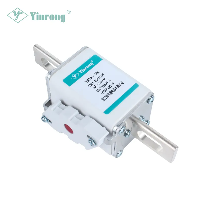
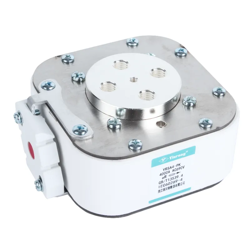
The YRSA series from Zhejiang Galaxy Fuse covers rated voltages from 690V to 1500V and rated currents from 10A to 3000A, featuring silver-plated pure copper or pure silver variable-cross-section fuse elements, housed in high-strength alumina ceramic tubes, with high-purity quartz sand as the arc-quenching medium.
3. I²t Coordination: The Core Parameter of Matching Design
I²t (ampere-squared-seconds) is the most critical quantitative indicator in fuse and contactor matching selection.
Selection Constraint Relationships:
|
Constraint Condition |
Technical Requirement |
|
Fuse let-through I²t |
< Contactor short-circuit withstand I²t |
|
Fuse pre-arcing I²t |
< IGBT/SiC module withstand I²t |
|
Fuse total clearing I²t |
> Downstream protective device pre-arcing I²t (to ensure selective coordination) |
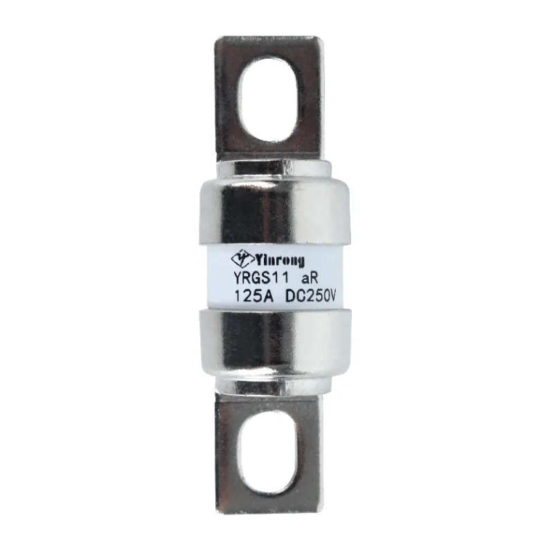
Galaxy Fuse's fast-acting fuse series features low I²t values, strong current-limiting capability, and high breaking capacity, making them suitable for short-circuit protection of semiconductor devices and complete equipment.
4. Time-Current Selective Coordination
In a multi-level protection architecture, the protective device closest to the fault point must operate first.
|
Fault Location |
Protection Action Sequence |
|
Output-end short circuit |
Fuse trips first (microsecond-level) → Contactor remains closed |
|
Controlled overload |
Contactor trips first (BMS command) → Fuse remains intact |
|
Contactor failure |
Fuse acts as backup protection, ultimately interrupting the fault circuit |
5. Ambient Temperature and Derating
Charging stations are deployed across a wide range of environments, with engineering requirements spanning from -40°C low temperatures to +85°C high temperatures. Both fuses and contactors must be capacity-derated according to actual ambient temperature.
|
Environmental Condition |
Engineering Recommendation |
|
Above 40°C operation |
Fuse rated value must be corrected per the manufacturer's derating curve |
|
High-temperature enclosed environments |
Contactor coil temperature rise requires dedicated verification |
IV. Galaxy Fuse: The Professional Choice for DC Charging Station Protection
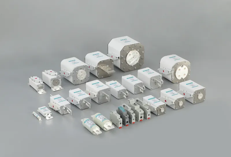
Founded in 1980, Zhejiang Galaxy Fuse Co., Ltd. is a professional fuse enterprise integrating R&D, testing, manufacturing, sales, and import/export. As a key enterprise under the former Ministry of Machine Building and a leading manufacturer of fuses in China, the company's main products cover photovoltaic DC fuses, new energy vehicle fuses, and charging station fuses. Products comply with IEC 60269, GB/T 13539.4, and other international and domestic standards, and are exported to over 80 countries and regions including Europe, America, Southeast Asia, and the Middle East.
Recommended DC Protection Product Series for Charging Stations
|
Application Position |
Recommended Series |
Key Parameters |
Certifications |
|
DC Output Side (aR protection) |
500V–1500V / 10A–1500A |
UL / TÜV / CE / CCC |
|
|
Battery Pack/Pack Protection |
DC 500V–750V / 10A–350A |
CE |
Galaxy Fuse's Core Technical Advantages
•Full-Series International Certifications: Multiple series have passed TÜV, UL, CE, and CQC certifications. Management systems cover IATF 16949, ISO 9001, ISO 14001, and ISO 45001.
•Mature Coordination Solutions: Extensive engineering coordination experience with mainstream DC contactors and mature selection solutions.
•Complete Technical Data Support: Provides measured I²t curves and cut-off current curves to facilitate precise coordination calculations with contactors.
•Deep Technical Accumulation: Holds over 48 utility model and invention patents for fuse product manufacturing, and was recognized as a national high-tech enterprise in 2017.
•Industry Standard Participation: Products comply with GB/T 13539.4, IEC 60269, and multiple other international and domestic standards.
V. Conclusion
The matching of contactors and fuses in DC charging stations can be technically summarized as: functional layering, timing coordination, and parameter interlocking.
•The fuse undertakes microsecond-level short-circuit current interruption to ensure the safety of IGBT/SiC and other power semiconductors.
•The contactor is responsible for controlled switching management, executing normal start/stop and emergency isolation commands.
•The two serve as mutual backup redundancy, forming a dual safety barrier.
When properly matched, each performs its own duties with layered defense; when mismatched, consequences range from protection failure to equipment burnout.
With over 40 years of dedication to high-quality fuse R&D and manufacturing, Galaxy Fuse is committed to providing safe and reliable circuit protection solutions for DC charging stations.
For technical support on fuse selection for DC charging station protection systems or coordination with contactors, please contact the Galaxy Fuse technical team.